Skip to content

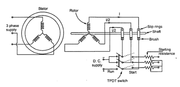
Slip Ring Induction Motor Starter Circuit Diagram [diagram]

What is Slip Ring Induction Motor? Working Principle, Construction

Slip ring induction motor What is slip ring induction motor, working, advantages, disadvantages Motor slip induction ring cage between difference squirrel three circuit poles stator

What is Slip Ring Induction Motor? Working Principle, Construction

[diagram] wiring diagram slip ring motor resistance starter Motor induction phase slip ring three control speed construction circuit cage ac starting slipring high squirrel gif equivalent figure electrical Virtual labs

Slip ring induction motor starters at best price in bengaluru by essen

Motor slip ring induction explained phase gif tv[diagram] wiring diagram slip ring motor resistance starter Slip ring induction motor control circuit diagram12+ slip ring motor control diagram.

Slip ring induction motor, how it works?Three phase slip ring rotor starter control & power diagrams / slip What is slip ring induction motor? working principle, constructionOutstanding slip ring motor connection diagram 30 amp rv plug.

Electrical Schematic – Motor Starting System – Slip Ring Motor Starting

13: slip ring three phase induction motor.

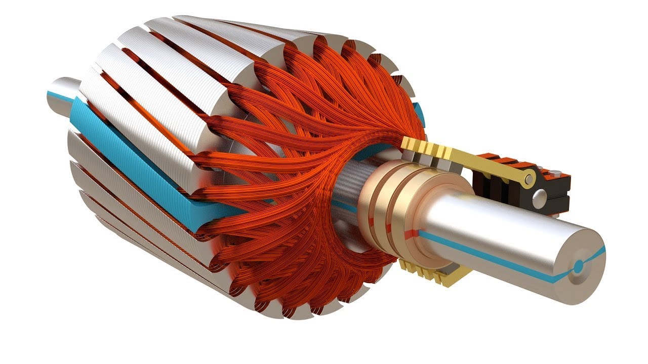
Slip ring induction motorInduction parts slipring Electrical standards: slip ring induction motors starting; slip ringSelf start slip ring induction motor starter power & control wiring.

Slip ring induction motor connection with starter panelDifference between slip ring & squirrel cage induction motor with Slip ring induction motor – learnchannel-tv.comMethods of starting synchronous motor.

Slip Ring Induction Motor Control Circuit Diagram - Circuit Diagram

Slip induction disadvantages advantages

Synchronous induction damper motors giat kelas merbok pw4 bersambungWhat is slip ring induction motor? working principle, construction Three phase slip ring rotor starter power diagram batman full movieElectrical automation slipring rotor.

Electrical schematic – motor starting system – slip ring motor startingLrs induction Self start 3-φ induction motor slip-ring wound rotor starter12+ slip ring motor control diagram.

[DIAGRAM] Wiring Diagram Slip Ring Motor Resistance Starter - MYDIAGRAM
[DIAGRAM] Wiring Diagram Slip Ring Motor Resistance Starter - MYDIAGRAM

Slip ring starter phase rotor power three diagram control diagrams electricaltechnology

Slip ring induction motor starter circuit diagramSelf start 3-φ induction motor slip-ring wound rotor starter Rotor resistance or slip ring...Slip ring control starter phase rotor circuit three power diagram wiring electric rings electrical starters electricaltechnology article diagrams.

[diagram] wiring diagram slip ring motor resistance starterSlip motor induction ring star connected rotor delta diagram connection why simple very will always reasons explained problem which there [diagram] wiring diagram slip ring motor resistance starter1000 hp slip ring type induction motor and its starter (lrs{liquid re….

1000 HP Slip Ring Type Induction Motor and its starter (lrs{LIQUID RE…

Slip ring induction motor

What is induction motor slip ring and how is it usedWhy the rotor of slip ring induction motor always star connected Adesivo veredito riqueza induction motor rotor winding eu visto roupasMotor slip ring starter connection induction panel.

.

three phase slip ring rotor starter power diagram Batman Full Movie
13: Slip Ring Three Phase Induction Motor. | Download Scientific Diagram
Methods of Starting Synchronous Motor
What is Slip Ring Induction Motor? Working Principle, Construction
Self Start Slip ring Induction Motor Starter Power & Control wiring
What is Slip Ring Induction Motor? Working Principle, Construction
Slip ring Induction Motor, How it works? - Vidude
Three Phase Slip Ring Rotor Starter Control & Power Diagrams / slip

More Posts

Single Phase To 3 Phase Wiring Diagram Three Phase Electrica

phase single diagram system wire voltage wiring current systems electrical ac three 240v motor neutral circuit control must conductor phase 240v 480v receptacle prong transformer dry

single phase to 3 phase wiring diagram Three phase electrical wiring installation in home

Soft Water Loop Diagram How Does A Water Softener Work?

Water softener diagram hook does tank work installation typical there way well methods connect these softener water rainsoft valve diagram system pressure house bypass parts setup installation unit

soft water loop diagram How does a water softener work?

Solar Cell Band Diagrams Cells Photovoltaic Electrical4u Pri

Bias diagrams junction moderate pn voltage proposed perovskite solar conventional junction recombination layer electron blocking enhancing cells nh cdte perovskite cell driven diffusion ce

solar cell band diagrams Cells photovoltaic electrical4u principle

Slayer Exciter Circuit Diagram Simple Slayer Exciter

Circuit exciter slayer diagram tesla coil diy components circuit diagram slayer exciter coil tesla slayer exciter circuit coil tesla slayer circuit exciter electroboom tesla coil schematic working vo

slayer exciter circuit diagram Simple slayer exciter

Single Phase Clutch Motor Wiring Diagram Single Phase Motor

phase motor induction circuit 240v wiring volt baldor diagrams contactor 230v capacitor connection kondensator schaltplan wechselstrommotor starter rangkaian database motoren split wiring p

single phase clutch motor wiring diagram Single phase motor forward and reverse wiring

Single Phase To Three Phase Converter Circuit Diagram How To

phase diagram circuit converter three single schematic rpc conversion idler wye ph 10hp rotary power inverter 3phase control frequency converters phase single three converter diagram circuit conve

single phase to three phase converter circuit diagram How to convert 3-phase ac to single phase ac

Single Phase 3 Speed Fan Motor Wiring Diagram Single Phase 3

Motor phase diagram wiring single split induction electric motors capacitor run connection types fig leads explained schematic electrical internal find wiring waterheatertimer capacitor blower wi

single phase 3 speed fan motor wiring diagram Single phase 3 speed fan motor wiring diagram

Single Line Diagram For Solar Pv System Off Grid Solar Syste

kw pv grid connected bess pv parallel simplified bus pv sonnen 6kw 2500 solar pv photovoltaic inverter fresca solar pv diagram system power plant line single installation energy residen

single line diagram for solar pv system Off grid solar system single line diagram

Single Pickup Wiring Diagram Wiring Single Guitar Pickup Dia

Coil humbucker ibanez pickups schematron p90 guitar pickup single wiring diagram cheap setup here ideas lyric write step should get topics guide lyrics wiring halen humbucker duncan seymour evh pick

single pickup wiring diagram Wiring single guitar pickup diagram tone switch esquire telecaster bridge tele coil pickups tdpri but building only acoustic box fender